2 Comments

As a part of a larger project I am working on at the moment, I have decided to invest in some new equipment for manufacturing / fabrication. This is the fourth in a series of posts where I will discuss some of the equipment I am looking at.

Today I will look at the topic of rotary tools. Specifically

The Dremel

While the Dremel company produces a range of tools, they are best known for producing a range of rotary tools (commonly referred to simply as "a Dremel"). In my case I own a Dremel 300 Series rotary tool. The set I purchased comes with a number of cutting, grinding, sanding, and polishing tools.

The kit I purchased also came with the Flexible Shaft Attachment. This can be particular useful for fine detailed work, as it means you don't have to support the full weight of the tool.

More recently I was given the WorkStation attachment. The effectively turns the Dremel into a small drill press. While not necessarily big enough for your typical drill job, when matched with a set of tungsten carbide drill bits, it does a excellent job of drilling homemade PCBs.


If you have any questions or suggestions, please leave a comment below.

11 Comments

A little while ago I decided to purchase a Roomba from iRobot for around the house, specifically the Roomba 570. It is a decision that I have never regretted. While it does not completely remove the need to vacuum the house, it picks up all those crumbs and bits of dust that accumulate over the course of a day. As an added bonus, the 570 (and some other models) come with a built in scheduler.  So in our case we simply set it to clean when we are not at home. By the time we get back the house is clean and the Roomba is back on its dock re-charging for the next day.
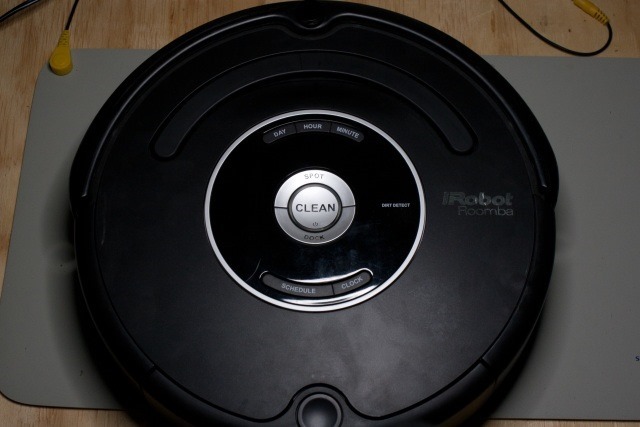
IMG_9191_640

(The Roomba on my workbench ready to be inspected)

Up until recently it worked day in, day out without ever complaining. Except for the time it got stuck under our bed, and to its credit, it just shutdown and waited to be rescued. This does makes for a fun game of hide-and-seek for my 2 year old son.

However, recently it started playing up a bit.  Occasionally we would come home to find it sitting in the middle of a room for no apparent reason (i.e. it was not stuck somewhere). When we would try to restart it (by pressing the 'clean' button on the top) it would report an error saying the brushes were jammed.  I would pick it up, look underneath, see everything was fine, and put it down and try to restart it again.  And off it would go quite happily, leaving me none the wiser as to what was going on.

Then one day when I put it down and sent it on its way I noticed a clunking sound coming from it.  Fearing this was not a good thing; I stopped it and checked it again.  Unfortunately it all looked fine.  After a couple of iterations of start, clunk, stop, check, restart, it would seem to come good, again leaving me none the wiser.

Well I finally decided to do something about it and have finally figured out what was happening.  The short version is that even if you follow the cleaning instructions as per the manual, you can still get build-up in places that will cause a problem.

Now, if your Roomba is still under warrantee, I strongly urge you to make use of that and contact support.  Having said that, fixing it is not that hard, and pretty much well within the realm of what they tell you that you can do in the manual.

Ironically, it was only after working out what the problem was (and fixing it), that I then decided to search the internet to see if anyone else was having the same problem.  And sure enough a simple search for 'roomba clunking' turns up a lot of information. However it should be noted that in my case, although the symptoms are similar, it actually had a different root cause to a lot of the information posted on the web. Oh well, it was a good learning experience on my part.

Below are the details of what I did to fix the problem.

Disassembly

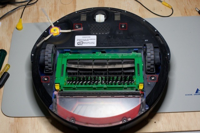
First of all, turn the Roomba over and remove the 5 screws shown below. Note that the screws are captive within the base plate, so they do not need to come all the way out.  Also, the side spinning brush will need to be removed as well (lifts off once the screw is undone). You can also remove the dust bin at this point.
IMG_9173_640

(The underside of my Roomba with the 5 screws highlighted)

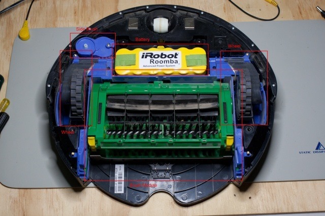
Once you have removed the base plate, you should be presented with the following.
IMG_9175_640

(The exposed underside of the Roomba)

Working clockwise around the image, starting from the top left, you have the following components:

  • Side spinning brush motor module
  • Battery
  • Left wheel module
  • Brush module
  • Right wheel module

After having a look at the way the Roomba has been designed and constructed, I am much more impressed than my initial impressions gave me. All of the modules listed above can be removed simply by undoing a couple of screws and lifting the modules upwards, making the whole process of replacing a module very simple for the owner. There has obviously been a great deal of thought put into the unit.

Now, back to my Roomba.

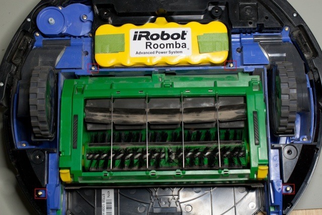
In this case, we are interested in the brush module.  If you wish to remove the module from the Roomba (to make it easier to work on), this can be easily achieved by undoing the 4 screws highlighted.
IMG_9176_640

(The 4 brush module retaining screws)

Examination

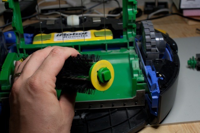
After removing the 2 brushes from the module, I noticed something unusual. The end plate of the brush that connects to the drive side of the module (the left hand side in the above image) had severe wear marks on it.
IMG_9184_640

(The brush endplate showing the wear marks)

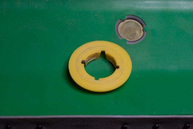
You can see the wear easier in the close-up.
IMG_9185_640

(Close-up of the wear on the end plate)

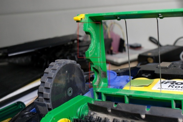
Further examination revealed signs of wear on the brush housing as well.
IMG_9178_640

(Wear on the inside of the housing)

Diagnosis

What I believed was happening (and was subsequently confirmed) was that something was pushing the brushes against the drive side of the module (where dirt was being trapped).  This in turn was increasing the torque required by the brush motor to turn, and the Roomba was detecting it as the brushes being tangled, and therefore trying to automatically correct for it (albeit unsuccessfully). Now the question is why are the brushes being forced against one side of the housing.

The Fix

A visual inspection of the brushes revealed no obvious cause.  However after comparing the brushes to the spare set I have in the cupboard, I noticed that the free spinning end of the brush was not spinning a freely as the 'new' brush (and if anything I would expect it to free up as the bush wears through use).

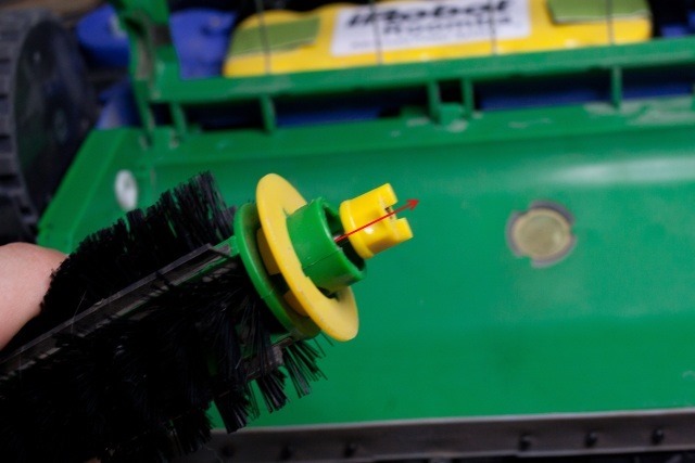
After a gentle application of brute force, I was able to remove the bush from the end of the brush.
IMG_9187_640

(Removing the bush from the brush)

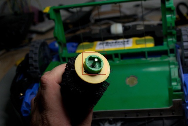
When looked behind the bush I found a large tangle of hair and threads wrapped around the shaft.
IMG_9189_640

(The exposed shaft)

It appears that there was enough stuff wrapped up behind the bush to start pushing the bush off the end of the rod, and consequently push the other side into the housing.  Once I cleaned out the end of the brush and replaced the bush, I found that the bush would spin far better than it was previously. I also took the opportunity to clean any other dust and debris from around the underside of the Roomba.

Re-assembly was simply a case of reversing what had previously done. Once I had it all back together I fired it up and worked perfectly.  At the time of writing this, it has been about 3 weeks and so far not a problem.

Additional Notes

Two things to note.  Firstly, after getting everything back together and working, I decided to have a search of the internet to see if anyone had come across a similar problem.  A quick search for "roomba clunking" revealed a number of posts dealing with the symptoms.  However, in all the posts I looked at, although the symptoms were similar, the root cause was different.

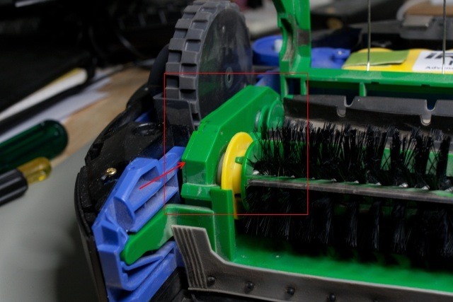
In the posts that I looked at, the cause was dust and dirt getting into the gear box that drives the brushes.  It appears that although the models are listed as being the same, there has been (at least) 2 revisions of the model.  In what I assume was an earlier model, the gearbox access panel did not seal against the case properly. My Roomba seems to have a different brush module with a different gearbox case design.
IMG_9179_640

(The gearbox case highlighted)

In the models show in the posts I was looking at, the gearbox access panel is a flat sheet of plastic that is simply held against the side of the gearbox with a couple of screws. This does not always appear to seal well, leading the dust getting into the gearbox.  On my Roomba they appear to have redesigned the access panel to have a lip that is recessed into the rest of the gearbox housing.  After inspecting the gearbox on my Roomba, there was virtually no dust or dirt inside. So the revised case design appears to provide a much better seal.

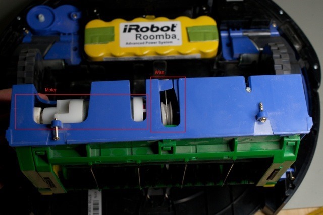
The second thing to note is that I believe I have worked out what the actual clunking that you can hear is.  Below is a photo of the motor in the brush module.
IMG_9190_640

(The brush module motor)

There are 2 items highlighted in the photo.  Firstly the motor, and secondly the wire. This wire is connected both to the motor, as well as the housing for the module (the blue plastic).

When the Roomba detects that it has a tangle in the brushes, it does a number of things

  • Reverses back the way it came
  • Runs the brushes in reverse
  • And lifts the brush module up off the floor to avoid getting re-tangled

It is the last item that is of interest.  When the brush motor runs in reverse, it is setup in such a way that it winds the wire up as well. This has the effect of lifting the brush module up off the floor.  This is also the source of the clunking sound you can hear. It's the inner part of the brush module (green plastic) hitting the outer casing (blue plastic).  Because of the higher load on the motor, the Roomba was continuously thinking it was tangled, it was constantly trying to untangle, and therefore kept pulling the brush module up. 

Mystery Solved.

0 Comments

As I mentioned in my blog, a little while ago I became interested in doing some high-speed photography. Now unless your freaky fast on the shutter, your just not going to be able to do it by hand. Instead you are going to need some additional hardware to achieve such a feat.

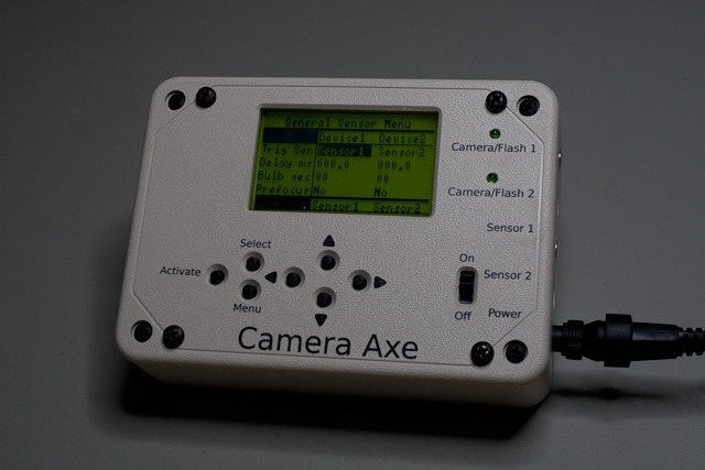
There are a number of offerings on the market and in my case, I chose to purchase a Camera Axe. Released under a Creative Commons license, the Camera Axe is an example of open source hardware (as well as software) that is also produced on a commercial basis.  At its heart it is based on a Amtel ATmega328 mounted to a custom circuit board. 

Part of what makes the Camera Axe appealing (at least to me), is the modular design that allows you to connect a variety of different combinations of triggers, cameras, and flashes.  While the Camera Axe is not the only offering to do so, in my opinion the available hardware provides a good range that will cover just about any scenario.

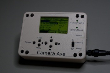
CameraAxe-Completed

(The Camera Axe)

Now, I did purchase mine in kit form from Dreaming Robots, but they do also offer pre-assembled versions as well (but where's the fun in that).

I also purchased the following sensors with the kit:

  • Projectile Sensor
  • Valve Sensor
  • Light Sensor
  • Microphone Sensor

As well as some miscellaneous cables (flash, camera trigger etc).

The Kit

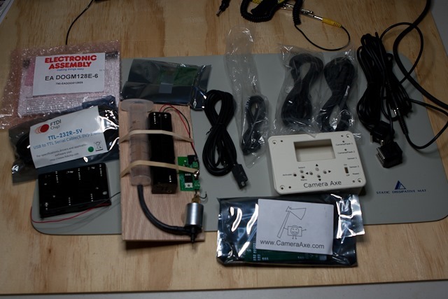
My order arrived well boxed and padded.  After opening the box and laying everything out, I had the following on my desk:

CameraAxe-Full-Bundle

(The unboxed bundle)

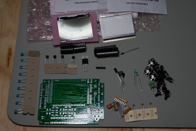
As you can see, the electronic components well all neatly packaged in anti-static bags, the other cables were also neatly bundled. After unpacking the main electronic components bag you get the following:

CameraAxe-Components

(The electronic components)

One item I did find interesting was the LCD screen included with the kit.  Visible in the top half of the about photo, it actually comes in two pieces. The LCD panel itself, and the backlight.

While the kit does not come with any printed instructions, both the builder’s guide, as well as the user manual, are available on the main Camera Axe website. While some people may be annoyed by this, I suspect it is done in part to keep the costs down and it also means that the latest instructions are available. In assembling the kit, I found the online builders guide to be well laid out (including the full list of materials for those who want to source their own components) with pictures to detail each step.

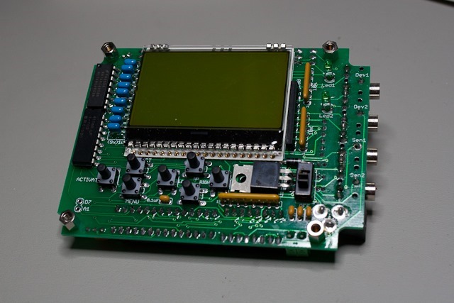
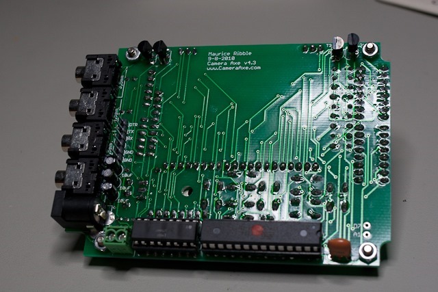
You can see the completed board below.

CameraAxe-Front

(Front of the assembled Camera Axe board)

CameraAxe-Back

(Rear of the assembled Camera Axe board)

I will go through some of the sensors that I purchased (as well as the resulting photos) in a future post....

2 Comments

A little while ago I became interested in doing some high-speed photography. I'm sure you've seen examples of such.  A bullet bursting through and apple.  A water balloon popping and leaving the water hanging in mid air.  Now unless your feaky fast on the shutter, your just not going to be able to do it by hand. Instead you are going to need some additional hardware to achieve such a feat.

There are a number of offerings on the market at the moment. At the basic level, most of them are an implementation of a delay timer that is started by some external input (i.e. the sound of a balloon popping).  In my case, I chose to purchase a Camera Axe. Released under a Creative Commons license, the Camera Axe is an example of open source hardware (as well a software).  At its heart it is based on a Amtel ATmega328 mounted to a custom circuit board.

Part of what makes the Camera Axe appealing (at least to me), is the modular design that allows you to connect a variety of different combinations of triggers, cameras, and flashes.  While the Camera Axe is not the only offering to do so, in my opinion the available hardware provides a good range that will cover just about any scenario.

CameraAxe-Completed

(The Camera Axe)

Now, I did purchase mine in kit form from Dreaming Robots, but they do also offer pre-assembled versions as well (but where's the fun in that).

I also purchased the following sensors with the kit:

  • Projectile Sensor
  • Valve Sensor
  • Light Sensor
  • Microphone Sensor

As well as some miscellaneous cables (flash, camera trigger etc).

So far I have only had an opportunity to play with the Valve Sensor to create water drop collision photos.

Studio Session-015

(Colliding water droplets)

0 Comments

As a part of a larger project I am working on at the moment, I have decided to invest in some new equipment for manufacturing / fabrication. This is the third in a series of posts where I will discuss some of the equipment I am looking at.

Today I will look at the topic of 3D printer.

3D Printer

From Wikipedia:

"3D printing is a form of additive manufacturing technology where a three dimensional object is created by laying down successive layers of material.[1] 3D printers are generally faster, more affordable and easier to use than other additive manufacturing technologies."

Since about 2003 there has been an increase in the number of different 3D printing products and technologies, as well as a decrease in the price of units. In the last year or two it is now getting to the point where it is possible and cheap enough for home hobbyist to consider obtaining 3D printing equipment. There are many choices out in the market today for 3D printing solutions, ranging from high-end commercial machines down to the home hobbyist (with the associated range of prices). One of the more well known names in the smaller end of the market is the Makerbot range of products. Their Thing-O-Matic kit gives you everything you need to get up and running for USD1299.

In my case, I have chosen to go a slightly different route.

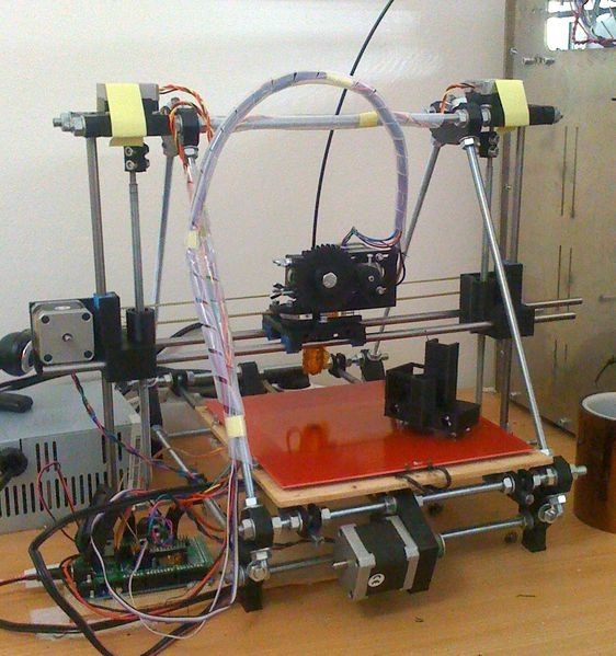
One of the other well known names in the 3D printing world is the RepRap Project. The RepRap Project has 2 main versions of their machine (although there are many variants). The first generation machine was called the Darwin.  The second generation machine is called the Mendel. My plan is to build a Prusa Mendel (a newer variant on the basic Mendel design).

562px-Assembled-prusa-mendel

(Image courtesy of RepRap.org)

Now you may have noted that I said build, instead of buy.  The reason for that is that the RepRap Project does not actually sell any hardware. Instead that is left up to 3rd party manufacturers. You can think of the RepRap Project as producing reference designs for others to implement. While there are a number of companies that produce Mendel's (either as per the original instructions, or their own variants) I have instead chosen to purchase the individual components myself from different suppliers.

There are 2 main reasons for this.  Firstly, the cost of the commercially produced machines tends to be higher (starting at around USD 800 and going up from there). Secondly, due to the nature of the RepRap Project, the design is constantly evolving and improving.  So the machine I am planning on building will not be a 'pure' Prusa Mendel.

(As a side note, the Prusa Mendel is a result of someone trying to improve on the classic Mendel design)

I will provide further details of what I am planning on building in future articles.

Now, I do have to point out that (as with the CNC mill) at the time of writing this, I do not yet have my kit. All the parts have been ordered and I am just waiting for them to be delivered. Once I have taken delivery of all my kit I will post more information.

If you have any questions or suggestions, please leave a comment below.